The optical parts are:
The primary, or main, mirror.
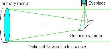
This is the large mirror in the bottom of the tube, with a concave, aluminized face figured to an extremely accurate paraboloid surface. It concentrates the light from a star into a sharp image - not really a point, but a diffraction pattern with a small circle of light surrounded by small, faint rings.
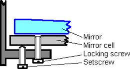
It is held in some kind of mirror cell, fancy or simple, that rests on 3 set screws. By adjusting these screws, you can finely adjust the tilt of the primary mirror, this is an important part of collimation (you only need to adjust 2 of them - it might be wise to leave the third in a middle position). Often there are 3 extra screws (or else springs) for locking the mirror cell in place, once it is adjusted. It may look something like this:
The secondary, or diagonal, mirror.
This is a smaller mirror with an elliptic face (its size is given as the length of its minor axis, i.e. its "width"). It is suspended by a spider with one or several vanes inside the tube near its opening, and the face is at 45 degrees to the tube. It is used to deflect the light from the primary mirror sideways, so that you can see the image without having your head in the way of the incoming starlight.
The secondary mirror holder, and often the spider itself, is adjustable. It can be (more or less easily) moved sideways and along the tube, and it can be tilted (or rotated) slightly. Commonly, the mirror holder has a center bolt and three screws for adjustment.
The eyepiece
This is a more or less fancy magnifying glass, used to see the image of the star or whatever else you look at. It has a certain focal length, and with several eyepieces of different focal lengths, you can select the magnification (often called "power") that you want. The focuser is where you put the eyepiece, it has a drawtube that holds the eyepiece and can be moved a little bit in and out, as needed to "focus" to get the sharpest view.
These optical parts are held in mechanical alignment by a tube of sorts. The tube, in turn, is supported by some mounting that lets you aim it at your chosen celestial object, and perhaps track its apparent motion as the Earth rotates.
How are they supposed to be aligned when the scope is well collimated?
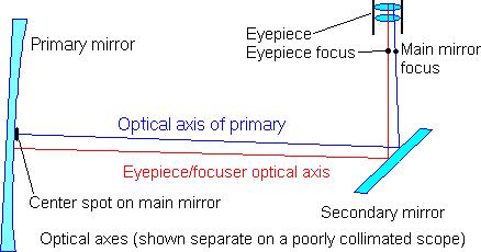
There are two optical axes in a Newtonian telescope: the optical axis of the primary mirror, and the optical axis of the eyepiece.
The axis of the primary mirror is perpendicular to the mirror at its optical center - for practical purposes assumed to be the center of the circular glass mirror. For convenience, this is often marked with a spot of paint or tape. The light from a star in the exact direction of the primary mirror axis will be reflected and "focused" to a sharp image at the focal point or focus on this axis. Other stars will form images around the focus, in the focal plane (actually, the focal "plane" is part of a sphere, with its radius equal to the focal length). The distance along the optical axis, from the mirror center to the focus, is the focal length.
The axis of the eyepiece is usually taken as the center of the focuser drawtube. The secondary mirror reflects the incoming light to the side of the tube, and here the focused image forms, and is seen with the eyepiece. The secondary will also "reflect", or rather deflect, the optical axes - it has an optical center, but no optical axis to concern us.
The main purpose of collimating is to align the two axes to form one common axis.
In most instruments, the focuser is fixed (or at least not readily adjustable), so it is practical to use the focuser axis as a reference. You first adjust the position and tilt of the secondary mirror to center the (reflected) eyepiece axis on the primary mirror, and then adjust the tilt of the primary mirror to center its (reflected) optical axis in the focuser. This done, the two optical axes are brought together.
Here comes some heavy theory - do I really have to read it?
Glad you asked - if you read this for the first time, you will probably find it a bit difficult to chew and swallow in one bite. So if you like, skip to the "End of heavy theory" for some more practical stuff. But I am sure the theory will make you understand the practical things better, and you may go back to read it any time later.
A systematic background:
I propose the following system of requirements for collimating Newtonians, and the corresponding errors, to facilitate understanding of the process (for illustrations, see the section on the corresponding errors)
The first and foremost requirement is:
- The two optical axes should be coincident, forming one common axis.
To simplify the error analysis, this can be broken down into two parts, giving separate kinds of error if violated:
1A - The optical axes should intersect at the common point of focus. 1B - The optical axes should be parallel.
When these requirements are met, and we can consider one common optical axis, the following supplementary requirements should also be met:
2 - The optical axis should strike the optical center of the secondary mirror. 3 - The optical axis should be deflected 90 degrees by the secondary mirror
4 - The optical axis (between the primary and secondary mirrors) should be centered in the tube.
A Newtonian telescope can be collimated to meet each of these requirements more or less closely, but as with mechanical adjustments in general, they cannot and need not be met exactly.
If we understand the effects of the separate errors, we can decide on the maximum error tolerances. We can then be sure that the telescope will perform as well as it should, if the collimation is done to within these tolerances. Here is a discussion of the effects of the errors:
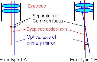
Error type 1A - The optical axes are separated at the focal plane
The eyepiece focus and the primary mirror's focus lie separated in a common focal plane.
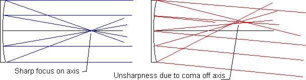
This is the crucial error for visual use. Images by the paraboloid mirrors of Newtonians can be close to perfect near the focal point, but suffer from increasingly severe coma at increasing distances from it.
Coma is an optical aberration that causes loss of contrast and detail resolution. It is approximately proportional to the distance from focus, and inversely proportional to the third power of the focal ratio f (this is the focal length of the primary mirror divided by its diameter).
Any good eyepiece gives a very sharp view near its focus - that is, in the center of the field of view. Towards the edge, however, all eyepieces cause more or less un-sharpness of star images. This is mainly due to astigmatism (I won’t explain that here) of the eyepiece - it is not the mirror’s fault - but shows up worse with a short focus mirror (with a low focal ratio). For most eyepieces, the coma of the primary mirror gives much less contribution to the un-sharpness.
If the focus of the primary mirror is in the focal plane away from the eyepiece focus, there will be some coma at the center of the field of view, where the image should be sharpest, and the image is not quite as clear and crisp as it could have been - particularly when you use high magnification to catch the subtle details of planet surfaces.
The "sweet spot" in the focal plane around the optical axis, where coma has limited effect even at high magnifications, could be surprisingly small. Also surprisingly, a large telescope mirror does not have a larger "sweet spot" than a small mirror - the diameter is an only a function of the focal ratio of the primary mirror, not its size. This table gives the diameter of the "sweet spot" where coma is less than 1/14 wavelengths RMS, and the Strehl ratio is lowered by no more than 0.2 (this corresponds roughly to the rather obsolete Rayleigh "quarter-wave" criterion of diffraction limiting).
Focal ratio�Diameter mm�
f/4�1.4�
f/4.5�2.0�
f/5�2.8�
f/6�4.8�
f/8�11�
f/10�22�
At the edge of this "sweet spot", coma may be noticeable in good atmospheric seeing, but within a circle of half this diameter, it would be very difficult ever to detect it (and the requirements for "good" seeing are stricter, the larger the mirror is). The small size of the "sweet spot" is of course one price you must pay for the convenience of a telescope with a large mirror, yet short, manageable tube, but it may not be as serious a drawback as it appears. In a "fast" f/4.5 telescope with high magnification, giving an exit pupil of 0.5 mm (this is 50x per inch of aperture, a reasonable upper limit at least for small telescopes), an eyepiece of "standard" field (some 50 deg apparent) has a true field of approximately 2 mm, the same size as the "sweet spot". But obviously, with short focus telescopes (low f/ numbers), centering the "sweet spot" within the eyepiece field of view is very much more critical than with the smaller, "slower" telescopes that were common before the "Dobsonian revolution". The "eyeballing" collimation, even today often found in manuals, may be good enough for a 6 in. f/8 telescope and yet fail badly when applied to a modern, large and fast instrument.
To decide on a reasonable tolerance for the 1A error, 1/4 of the diameter (half the radius) for your f/ratio could be a reasonable goal - for a small, dedicated planetary scope, you may want a little closer tolerance such as 1/6, but for a large, fast Dob where the seeing will usually limit the resolution, you could allow 1/3 or even 1/2 of the diameter. See later how you can use the Cheshire (the barlowed laser is similar in this respect) or the laser collimator to decide when you are within your tolerance.
If you have a center spot that happens to be at a distance D from the true optical center, and do a perfect collimation against it, the collimation error 1A at the focal plane is half the distance, or D/2. Thus, for critical collimation, the allowable miss centering of the center spot should not be more than the diameter of the "sweet spot", and preferably less than half the diameter.
Error type 1B - the optical axes are not parallel, but form an angle.
This type of error means that the focal plane of the eyepiece, or the plane of a film or electronic detector, will be tilted relative to the focal plane of the telescope.
Let us assume that collimation of the primary is perfect at the center of the field of view, but the focuser's axis misses the center of the primary by a distance b. This means an angle of tilt = b/F where F is the focal length (in radians - multiply by 57.3 to convert to degrees). At a point a distance m from the center of the field of view, the defocusing distance d between the planes is dm/F. The P-V defocus error in wavelengths is (Suiter): dm /(8Ff2*λ) where λ is the reference wavelength of 550 nm - to obtain the RMS error, this is further divided by √12. If this error is no more than 1/3 of the unavoidable coma, it means it will not contribute more than 10% to the total wave front deviation - even disregarding other contributing aberrations such as curvature of the focal plane of the primary but also of the eyepiece, as well as off-axis astigmatism of the eyepiece itself. Coma will give an RMS aberration of 6.7m/f³, this leads to the tolerance d=0.034D where D is the mirror diameter, (rather surprisingly, the focal ratio and focal length are eliminated from this expression!) or about 1/30 of the mirror diameter. This should not be difficult to meet.
However, to reduce coma in large, fast telescopes, a coma corrector such as the Paracorr (by TeleVue) is often used. It will reduce coma by a factor of about 6. In this case, the tolerance should be 1/180 of the mirror diameter. This can be met with a laser or an autocollimator, but may be difficult with just a sight tube.
An error of type 1B may cause an error of type 1A, if the collimation tool is used far from the focal plane, making the optical axes intersect at a point far from the focus. If the tolerances above are met, this should not be a significant problem.
In this estimate of tolerances, the aberrations of the eyepiece itself have been ignored, although they can be the dominant aberrations visually. Any eyepiece will have a spherical aberration that increases rapidly with decreasing f/ ratio. If this spherical aberration is strong, a tilt of the eyepiece may cause astigmatism - this is not readily calculated, but I believe the effect is insignificant if the tolerances above are met.
It has been suggested that an eyepiece in a Barlow lens, or an eyepiece with a similar negative first element built in, may be more sensitive to an error type 1B. This is not so - if the optical axis was centered in the focal plane without the Barlow, it will also be centered in the new focal plane of the Barlow, even if the combination is slightly tilted.
Error type 2 - the optical axis strikes the secondary mirror at a point away from the optical center.
The secondary mirror has an elliptical surface with a major to minor axis ratio equal to the square root of 2, for 90 degree deflection. Depending on its size, it lets some of the focal plane be fully illuminated, that is any point within the area of full illumination sees the whole primary mirror reflected in the secondary. Outside of this, some light is lost.
Due to the 45 degree tilt, the elliptic surface appears circular when you see it with your eye centered on the optical axis near the focus. However, due to the perspective, the center of the circle you see is offset from the geometric center of the ellipse, towards the edge nearest to the focuser. To be optically centered, the secondary mirror must be offset both in the direction away from the focuser and towards the primary mirror. The offset in each direction can be calculated with very complex formulae, but the formula offset=minor axis/(4*focal ratio) is accurate enough for practical purposes (it is exact if just the center is fully illuminated - with a larger fully illuminated field, the error is insignificant anyway). The distance along the mirror face from the center of the ellipse to the optical center is the offset multiplied by
1.414 (the square root of 2).
Example: with a 33 mm secondary mirror (the size refers to the minor axis) in an f/6 Newtonian, the offset is 33/(4*6) mm = 1.3 mm.
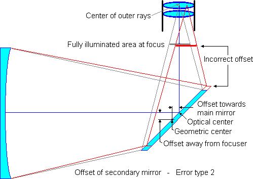
An error of type 2 causes the fully illuminated field to be offset relative to focus, and will cause an
uneven light loss near the edge of the low power field. For wide-field photo, the secondary mirror should be large enough to let the whole film frame be fully illuminated, but for visual use, a secondary size of no more than 20-25 % of the primary mirror diameter is commonly preferred, in order to minimize unwanted diffraction effects. This means there is usually some light loss by the edge of the field, but at least the focus should always be fully illuminated - the tolerance should not be larger than the radius of the fully illuminated field. At least for short focus instruments, light loss is very gradual outside the fully illuminated field, and an offset of a few millimeters should have little effect visually. Sufficient accuracy is easily achieved with suitable tools.
To calculate the secondary size or the size of the fully illuminated field: let D be the diameter of the primary mirror, d the diameter (minor axis) of the secondary, F the focal length, b the distance from the optical center of the secondary to the focus, and x the diameter of the fully illuminated field: x = (Fd-Db)/(F-b) or d = x + b(D-x)/F
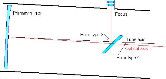
Error type 3 - the common optical axis is not reflected at 90 degrees.
Standard secondary mirrors and holders are designed for 90 degree reflection, and seen from the focus the elliptical mirror appears circular. An angle of more or less than 90 degrees will make it appear slightly elliptic - and the fully illuminated field will also be somewhat elliptic. If you have collimated, but the holder is not parallel to the optical axis, the reflection of the secondary holder may look visibly skewed. If so, you should consider shimming or otherwise "squaring" the focuser. An error of type 3 will have no other effects on the image (contrary to common belief).
Error type 4 - the common optical axis is not centered in the tube.
If the axis is grossly decentered, the tube opening may cause some (very mild) vignetting, and this should of course be avoided if possible. Otherwise, it will have no optical effect. It may cause problems with some mounts, as an offset axis will not trace a great circle when the tube is moved in declination. This might introduce some error when using digital setting circles. For exact centering of the optical axis, the secondary mirror must be correctly offset, and the primary mirror must also be accurately centered.
End of heavy theory - at least most of it.
So what steps do I take to collimate my telescope?
The lining up of the optical components should be done in a sequence that is as simple and ordered as possible. Ideally, you would start at one end of the optical chain and then proceed in steps to the other, without going back to readjust what once was adjusted. With real telescopes this is not possible, the adjustments affect each other in different ways depending on design details. For instance, with common secondary supports, it is not possible to adjust the tilt without moving the optical center significantly.
One practical way is to do it in the order described below (you could perhaps do it in the opposite order, but I believe it is much more complicated). Remember that this refers to a full collimation, like when you assemble the telescope from parts - you do not have to go through all of this just to get your telescope ready for the night’s observing! With a truss tube that you assemble at the observing site, you should do step 4, else step 5 (and maybe step 8) is usually quite sufficient for this.
The tools will be described in a later section, with details of their use. The error numbers are explained in the section on theory that you may have skipped.
In the first three steps, you place the focuser and secondary within the upper end of the tube. You can use a simple or combination sight tube, as described below. You may also use a crosshairs sight tube or a laser collimator.
- Square the focuser
If the focuser appears to be squarely mounted on the tube, it is not likely to be badly off - however, if you find it impossible to perform step 3, this could be the reason. You can make a small mark directly opposite the focuser hole. With the secondary mirror out of place, use a sighting device in the focuser.
Shim the focuser to center the mark. A piece of tubing that fits your focuser, long enough to reach across the tube, will make it even easier, and so will a laser collimator or a crosshairs sight tube. (This minimizes the error type 3)
2 - Center the secondary mirror within the tube
You should check the centering of the secondary mirror side-to-side as seen from the focuser - if it is off by more than you think it ought to be (a few mm perhaps), adjust it and go back to step1 and shim the focuser as needed. If you like, and if it is simple to do with the spider you have, you can also offset it from the center of the tube, in the direction away from the focuser. Calculate the offset, and use a ruler, or else wait and adjust (and re-collimate) after step 6 is done. If you cannot offset the secondary, e.g. because of the spider design, you may leave it centered in this direction, too, without serious consequences. (This minimizes the error type 4)
3 - Center the secondary mirror along the tube
To center the fully illuminated field of view, the secondary mirror should be offset towards the primary mirror, as seen from the center of outer rays (this is the point where the primary mirror appears to exactly fill the face of the secondary). If you center it as seen in a sight tube, it will automatically be correctly offset towards the primary. A holographic laser collimator with a wide enough pattern could also be used.(For fully offset collimation, the secondary should also be offset away from the focuser as described in step 2.) If you want non-offset collimation, you could put a small spot at the geometric center of the secondary and center it on the laser beam.
If you find that the secondary is offset "sideways", away from the tube axis despite your efforts so far, you may have to go back to either step 1 and shim the focuser sideways or to step 2 and adjust the spider setscrews.
(This minimizes the error type 2)
4 - Tilt the secondary mirror to make the extended optical axis hit the center of the primary mirror.
Use the appropriate setscrews on the secondary mount - depending on the design, you may also rotate the secondary holder to center "sideways". You can use a single or double crosshairs sight tube, by centering the spot on the crosshairs. You could also use a simple or combination sight tube, by centering the primary mirror within the sight tube end (if you don’t have a center spot, this is one way, another is with a holographic laser). Perhaps the most convenient tool is the laser collimator, making the laser beam hit the center spot. If you plan to use the laser also in step 5, it is imperative that the centering is very accurate, else you only need to make sure the error is no more than perhaps 1/300 of the focal length, or 1-2 percent of the diameter of the primary.
If you can rotate the secondary, you could get it skewed by tilting it one way, and rotating it the other. If you see the secondary or its reflection looking skewed, try straightening it up, then rotate it to get the primary mirror roughly in line. Then start over with this step, but do not rotate.
If you have made major adjustments, go back to step 3 (and possibly step 2) and check that the adjustments still are OK, or adjust if needed.
If the primary mirror is badly out of adjustment, part of its edge may appear obscured by the tube opening. If this makes centering difficult, go forward to step 5, and make a coarse adjustment before going back to step 4 again. (This minimizes the error type 1B.)
Going forward from here, do not skip step 5!
5 - Tilt the primary mirror, to center its optical axis in the focuser.
If you have a mirror cell that holds the mirror very loosely (this is particularly common in Dobsonians), you may make the mirror settle by tilting the tube nearly horizontally, and then raise it, before you go on.
Here you use the set screws to adjust its tilt (use 2 to adjust, and leave the 3rd - else you may find, after some time, that all are near the end of their range), and thus the tilt of its optical axis. You could use a Cheshire or a combination tube, by centering the primary mirror spot in the bright spot of the Cheshire (if you use the calibrated Cheshire, you will know that the error type 1A is within tolerances, when the black spot is surrounded by an unbroken ring of light). You may even use a peephole with a semi-transparent lid as a primitive Cheshire, if you illuminate it from the outside. To minimize any error from a possible miscollimation in step 4, do not place the Cheshire far from the focal plane - near the edge of the focuser drawtube at its usual position.
If you can reach to adjust the collimating screws while looking into the Cheshire, this simplifies things enormously! I have built my own telescopes so that I can, but with most commercial telescopes, this is not possible. The next best thing is an assistant to turn each screw in each direction while you note the effects. A simple trick is to put a sticker near the focuser, where you draw two arrows to mark the direction that the spot appears to move when you turn each screw inwards - this way, it is easy to decide what screw to turn in what direction.
You can use a laser collimator (and a perforated center spot) to get close, but as the precision is entirely dependent on the accurate centering of the spot in step 4, it would be wise to check - and if necessary, fine tune - with a Cheshire, unless you are quite confident this was done very accurately. Another way to get high precision is using a combination of laser collimator and Barlow lens.
If you have no center spot, you can use a double crosshairs tube - see here how.
I like a fairly large spot, not very much smaller than the bright face of the Cheshire. What I see is a thin ring of light, and I can readily detect even a small asymmetry. Others like to align against the center hole of the Cheshire - for instance by using a square mirror spot, its side a little smaller than the opening, its corners protruding outside it. A donut-shaped ring may be fine if its inner diameter is a bit larger than the opening in the center of the Cheshire - any way is fine as long as you can match the positions accurately.
(This step minimizes the critical error 1A)
6 - Check the centering of the optical axis in the telescope tube and in the focuser drawtube.
A coarse test is to look through the empty focuser tube and check if you can see the outer tube end reflected in the primary mirror from any point within the focuser. If you can’t, the centering is OK optically.
If you have reason to do better, you can make a centering mask, and check with a peephole (or Cheshire or sight tube) whether it is well centered relative to the primary mirror. If you need to adjust, move the spider the required amount away from the visible part of the centering mask (put your finger inside the tube opening to see which direction it is), and start over from step 3. (This checks the error type 4)
7 - Star test
The whole purpose of collimating is to get the best images of stars and other celestial objects. You may want to check the collimation by looking at a star - use a magnification of 1-2x per mm of aperture
(25-50x per inch). Do not trust this step unless the seeing is good enough to clearly discern the diffraction rings.
Center a star in your field of view (the centering is important! You may use Polaris if you live far enough North and have a telescope with no tracking facilities). Gently rack the focuser from one side of focus, passing the focus, going to the other side.
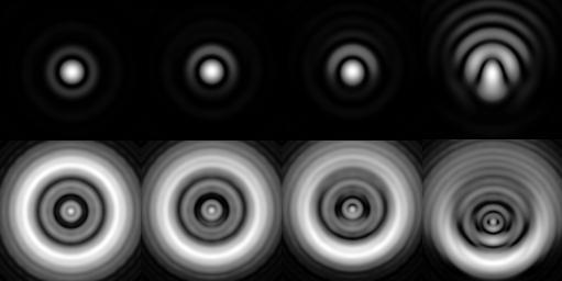
These simulated images show (top row, left to right) the star images in perfect seeing: At the center
At half the radius of the sweet spot the full radius
2.5 times the radius.
The lower row shows defocused images of the same. The star test is most sensitive near focus. (Simulation program: Aberrator by Cor Berrevoets. There is some spherical aberration as well as a secondary obstruction).
If you can work the collimating screws while looking in the eyepiece, fine - else find an assistant to work the screws by your commands. Doing it all alone can be frustrating.
If there is a marked asymmetry, try and see if the image improves if you place it off center in any direction. If so, try to tweak the primary mirror to move the image towards the center of the field, in steps until it looks symmetric (If you start with a nearly perfect collimation, it will save you a lot of tweaking).
It is possible (I don't know how likely) that the optical center of the primary mirror is not at its mechanical center. If you star collimate and afterwards find that the center spot is consistently offset in the Cheshire, this is no doubt the reason. If so, first star collimate, then move the spot to appear centered in the Cheshire (or at least remember how far it is off, and in what direction). Once this is done, the Cheshire should give consistently good collimation.
- Check the finder and adjust if necessary
If you have tweaked the collimation, you may have shifted the optical axis slightly, and the finder is no longer accurately adjusted.
If your telescope is new, or if you have moved the spider, you can check that the spider veins have not been tilted or twisted during collimation. Look down the tube and move your eye to see each vane look its thinnest, and check that you see it centered against the mirror (if the vane is centered - otherwise, check that you see it over the corresponding part of the mirror). If offsetting the secondary mirror makes the vanes slightly out of line, or out of perpendicular, this may make the diffraction spikes look less distinct or pretty, but it does not affect the sharpness or contrast of the image.
You can also check that the collimation holds at elevations from some 20 degrees to zenith (some primary mirror mounts, where the mirror isn’t glued or clamped, will not hold the mirror firmly enough to use all the way down to the horizon). If the collimation cannot be kept within tolerances, there is some weakness in the tube. It may be the primary mirror support, but it may also be the spider or the secondary mirror mount that is not rigid enough.
Does this procedure give offset, or non-offset, collimation?
It seems that there are widespread misconceptions about secondary offset, or at least different ideas about what it should mean.
If you dot the geometric center of the secondary mirror face, and center this dot in the focuser (using a crosshairs sight tube or a laser collimator) and also center it inside the tube, you will get a truly non-offset secondary. This has been recommended, but it will give an error (usually acceptable) of type 2, and I don’t see that it would be simpler, or offer any other practical advantage. (If you use a holographic laser, the shadow of the secondary can only be centered in the pattern with non-offset - or non-existent - collimation. Some manufacturers recommend you to check this centering as a last step of collimation, but I believe it is better not to).
If you have optically centered the secondary in a sight tube as described above (step 3), it will be correctly offset along the tube. But what happens if your secondary is centered within the tube, without offset away from the focuser in step 2? This is sometimes called "non-offset collimation", or "neither centered, nor offset, but a compromise" (Menard/D’Auria: Perspectives on collimation).
Once the point is set where the focuser axis hits the secondary (be it at the optical or mechanical center, or any other point), the further collimation of the primary mirror ensures that the combined optical axis will return to hit the secondary at that very point again. Thus, if the optical axis hits the optical center of the secondary, but it is the geometric center that is centered within the tube, it means that the optical axis will be offset from the tube axis - an error type 4 (it may also lead to some small error type 3). But since the offset is typically only 0.5-1.5% of the aperture, the error is of little or no significance. Thus, if the design of the spider is such that you cannot easily offset the secondary, you may leave it centered in the tube.
What tools can I use to make the collimation easy and accurate?
Here are some useful tools. You can make some (or all) of them yourself, see the do-it-yourself section (or follow the links) for details. Some of my designs there allow full control of tolerances - you can see immediately whether or not your collimation is within the accepted limits.
Tectron makes a set of 3 tools: crosshairs sight tube, Cheshire and autocollimator. Orion makes a combination tool (Cheshire + crosshairs sight tube). I have no personal experience with these. Several manufacturers make laser collimators. Whether you prefer a laser or a sight tube, a Cheshire can also be helpful.
The primary mirror center spot.
This is a small (but not too small) circle (square or even triangle is OK, too) of tape or paint placed in the center of the mirror - it is invaluable. Please note that it is always in the shadow of the secondary mirror, and does not interfere with the image. Regrettably, manufacturers often omit it, and if your mirror doesn’t have one, I recommend you make one.
Hey - it isn’t even my own ‘scope and anyway I wouldn’t dare take it to pieces and risk putting my fingerprints all over the mirror - isn’t there another way?
Yes, I have a solution - not quite as neat as if you have a spot, but it will do the job. Breathe again.
Should I center spot my secondary mirror?
Unlike the spot on the primary mirror, a spot on the secondary could affect the image - and even obscure the primary mirror center spot. I suggest you don't (unless you have a compelling reason).
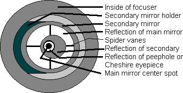
The peephole
This is a small cap that fits in the focuser, with a small center hole (1-2 mm or so) to look through. It is easy to make one. You can adjust the collimation to make the following appear concentric (from outside in):
The inner end of the focuser drawtube
The secondary mirror (not so easy to see, since the outer edge reflects the black interior of the tube) The primary (main) mirror reflected in the secondary
The reflection of the secondary mirror - but note that this image (and only this) is not concentric. The reflection of the drawtube and peephole cap (if transparent or semi-transparent - if not, it will be too dark to see).
The mirror spot
The eyeball centering (commonly described in handbooks) can be done with a peephole tube, but the precision is low and you have no control of the tolerances (that are more critical for short-focus optics). A semi-transparent peephole cap may be used as a Cheshire substitute (see later) in step 5, and with care and luck, the result may be good enough - and a lot better than if you did not try at all.
It is even possible to do this entirely without tools - you just hold your eye near the focuser drawtube, as well centered as you can. You might line up things more or less, but you are unlikely (more so, the "faster" your telescope is) to get the centering of the spot accurately enough (error 1A), so at least use a peephole when tweaking the primary mirror - or use star collimating to fine tune.
If the secondary mirror is correctly offset towards the primary mirror, it will appear centered when seen from a point near focus - but if you move your eye far away from focus, you will no longer see it centered. If you have the secondary mirror truly non-offset, it will appear to be offset away from the primary mirror, but its reflection is centered instead.
The simple sight tube
This is a piece of tube with a peephole cap. To center the secondary mirror, the length is not very critical. If the length is close to the inner diameter of the tube times the focal ratio of your telescope, you could also center the primary mirror within the inner opening of the tube. Here is how to make one.
You cannot, of course, see the inner opening and the mirror edges perfectly sharp at the same time, but the small peephole will improve your "depth of focus" and keep the un-sharpness tolerably low.
To center the secondary mirror (step 3) you can hold a strip of white paper (or a L-shaped piece of cardboard, as shown below) inside the tube, below the secondary mirror (with a truss tube, you can use the lid of the mirror box). You see the whole of the secondary face reflecting the white paper - without it, the outer rim of the secondary will reflect the dark inside of the telescope tube around the primary mirror, and what you see is the edge of the primary, not the secondary. Move the tube in or out (be careful not to hit the secondary with it!) to make the secondary appear barely smaller than the tube opening, and lock it with the focuser locking screw. Move the secondary (try to avoid changing the tilt) to center it accurately
- or at least to within acceptable tolerances. To center it "sideways", you may have to move the spider veins - if this is not possible, shim the focuser sideways instead.
To center the primary mirror (step 4), take away the paper strip/cardboard (or take the lid off the mirror box) and push in the tube far enough to see the primary (main) mirror reflected well within the secondary. Tilt the secondary (try to avoid moving it) to center the primary mirror inside the tube opening (or inside the secondary, if that is easier), just as you centered the secondary.
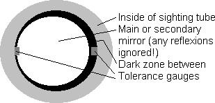
To aid in checking tolerances, you could put small protrusions inside the tube at its inner end (I have used strips made from the tubing, 2 mm high and slightly wider and longer). These act as tolerance gauges - if you divide the height by the tube length you get the angle in radians (multiply by 57.3 to get degrees) that the gauge is seen by. My f/6 tube is 168 mm long and the gauge is 2 mm high, the angle is 0.68 degrees (approx. 2/3 degrees). If I have centered as shown above, and the black rim is almost gone at one side and as high as the gauge at the other, then the error type 1B is half of the angle, or 1/3 degree - this is usually acceptable but I would try to halve this error.
To judge the centering of the secondary, you can multiply the gauge height by the ratio (secondary size)/(inner diameter of peephole tube). If secondary size is 84 mm and inner diameter of tube is 28 mm, errors should be multiplied by 84/28=3.0. In the illustration above, error is half the gauge height times the multiplication factor - that is ½*2*3 mm=3mm.
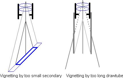
On some telescopes, it may not be possible to center the mirrors as described. If the focuser is too tall and/or the secondary is too small, you cannot see the edge of the primary mirror inside the edge of the secondary. If the drawtube is too long and/or the secondary is too big, you cannot see the edge of the secondary to center it. In both these cases the basic design is flawed (unfortunately this is rumored to happen sometimes with commercial telescopes), and if you are an Amateur Telescope Modifier you might consider modifying it. Otherwise, you may use a crosshairs tube as described below - your telescope may give a very good performance, nonetheless.
The crosshairs sight tube
This is a peephole tube with crosshairs at the inner end, for centering the optical parts. Here is how to make one. A single cross is fine for aiming at the primary mirror center spot in step 4 (this works even if you can't see the rim of the primary mirror). You can also use it in step 3 to center the secondary, if there is a spot at its optical center. This works with a focuser drawtube that is too long to show the edge of the secondary mirror with a simple sight tube. It is also useful in step 1.
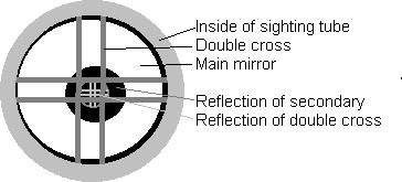
A sight tube of the right length to center the primary mirror in the inner opening (see simple sight tube) and with an accurately centered double cross can be used to collimate a telescope that (for any reason) does not have a center spot on the primary mirror. In step 4, center the mirror within the inner opening as carefully as possible, and then adjust the primary mirror to make the reflection of the crosshairs centered within the crosshairs themselves (step 5) - you may have to illuminate the crosshairs from within the tube using a flashlight:
A holographic laser may also be used in this situation, by accurately centering the holographic pattern on the primary in step 4 - then do step 5 as usual.
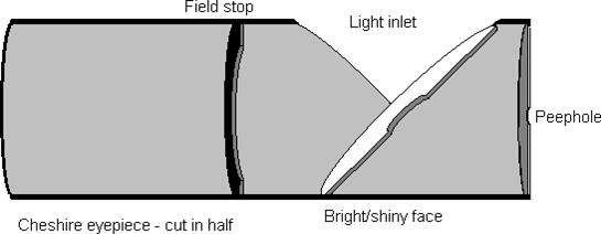
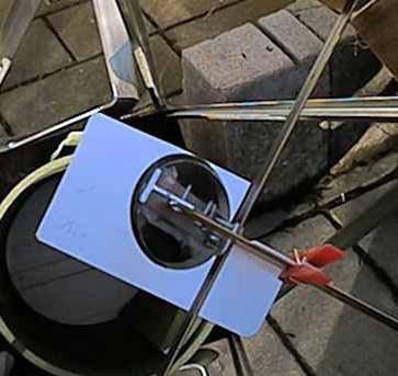
The Cheshire eyepiece
This is a development of the simple peephole tube, with an illuminated face (white or shiny) set at 45 degrees. A hole in the side of the tube lets in daylight (or suitable night light, like your chart-reading light) to make the reflection of the center spot visible against the bright face. There may be a "field stop" to define better the edge of the bright area. Here is how to make one.
The Cheshire eyepiece is used in step 5 (see above) to minimize the type 1A error. Collimation (usually of the primary mirror) is tweaked to make the spot appear centered within the bright area. Naturally, you try to center it "exactly", but as the following example shows, it is possible to estimate the error.
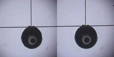
These images were taken through a combination sight tube - the offset of the secondary relative to the black center spot is obvious in this f/4.35 instrument. The spot is 15 mm dia. and the bright face 25 mm. In the first image, the edge appears to vary from approx. 2 to 8 mm - this is 3 mm offset, or 1.5 mm error type 1A at the focal plane, this is not acceptable. In the second image, the width varies from 4 to 6 mm i.e. 1 mm offset or a 0.5 mm error type 1A. I would accept it.
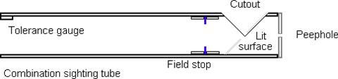
The combination sight tube
This is simply a peephole with the eye end rebuilt as a Cheshire - either cut it to size like a simple sight tube, or with crosshairs at the opening, or both. I prefer a home-made combination (as in the image below, cut to the appropriate f/ ratio - if you buy one, it is likely a one-size-fits-all, with crosshairs), as it can adequately handle the important steps 3, 4 and 5.
The laser collimator
WARNING: Never look at any laser beam directly! Normally, the beam will stay within the optical path of the telescope, but if it is badly out of collimation, the returning beam may escape beside the secondary. Do not look down the tube if you don’t see it return as expected - instead, try picking it up on a piece of paper in front of the tube.
This is a solid state laser, mounted in a tube to fit the eyepiece holder, and critically collimated to make the laser beam centered in (1A) and parallel to (1B) the tube. The "inner" end has a bright face where you can see the spot of the returning beam, with a small hole for it to exit. It can be used in steps 1, 3, 4 and, with reservations, step 5. Some models have the face at a 45 deg angle (a bit like the Cheshire), visible from a distance through a hole at the side of the assembly.
The laser collimator can be expensive and impressive, and favored by many. It makes step 4 very simple, as you can stand by the tube opening and easily see where the beam hits the primary mirror while you adjust the screws on the secondary holder. Seeing where the beam returns can be harder, particularly if the returning beam has been focused by the primary mirror to make the spot smaller than the exit hole.
One trick is to see the scattered light where the beam hits the secondary on its two-way trip.
Some laser collimators are sold with a holographic attachment, projecting a reticle that covers a fairly wide angle. This may help in step 3, where you can see the centering of the reticle on the secondary (particularly if you use the L-shaped cardboard piece to project the pattern), and possibly also step 4 and
6. However, contrary to what some manufacturers claim, it is not very useful in step 5.
Potential problem using a laser to collimate the primary mirror:
After step 4, if the laser beam is off the primary mirror center, the return beam will be parallel to the optical axis, but displaced (by the same amount) at the return. If you then adjust the primary mirror to center the return beam accurately, you unwittingly miss-collimate and get a 1A error (of half the displacement). For instance, a critical tolerance for a f/4.5 mirror may only be some 0.5 mm or 0.02 in., so the allowable error in step 4 should be much less than twice this (1 mm or 0.04 in.). With many telescopes, it is not really possible to read the position of the spot (or even adjust the secondary holder) to anywhere near the required precision. On the other hand, if you allow a type 1B error of 0.2 degree (assuming a 70" = 1.8 m focal length), the spot can be 1/4 in. or 6 mm off!
(In other words, the 1A error after collimating with a laser is half the vector sum of the offsets at the primary and at the face of the collimator.)
For this reason, if you collimate step 5 with a laser, you should make very sure you have centered the spot very accurately in step 4 - or else check with a Cheshire (or even star test) that the collimation is acceptable, and tweak it if necessary. In the section on Experimenting, I have described a workaround.
You can make your own laser collimator from a cheap keychain laser pointer.
The autocollimator
The name may suggest that this is a device that will automatically collimate your telescope - sorry, but it won’t. It is another development of the simple peephole tube, with a mirror inside the cap. There is a transparent spot in the center of the mirror, used as a peephole, and the mirror is set accurately perpendicular to the tube (there are other devices called "autocollimator" too - if you search the net for more info, don't be confused).
I have had a rather skeptical view of it, mostly because I have found the instructions unclear and to some extent unreasonable in claims. During this discussion, I tried to derive exactly how the reflections seen in an autocollimator relate to miss-collimation.
In brief, you may see 4 reflections of the center spot (if illuminated!), all of them stacked on top of each other if collimation is perfect but offset from each other if either the focuser or the primary axis (or both) is miss-collimated. This is shown with high sensitivity, but since it is the combined error that is shown, it is not readily apparent what to adjust!
However, if you have collimated the primary as accurately as possible using a Cheshire or Barlowed laser, any errors shown will be of the focuser axis (particularly if aligned with a sight tube), and gentle adjustment of the secondary (or better the focuser, if adjustable) will bring down the 1B error to the same low level as the 1A error already minimized. It can also be used as a "sanity check" - if, after careful collimation, the autocollimator shows significant miss-collimation, it would indicate a problem somewhere in the procedure - or perhaps a tool such as a laser collimator out of adjustment.
The centering mask
Take a piece of paper or semi-transparent plastic, large enough to fit over your tube opening. Make a circle exactly as large as your primary mirror, and center it over the tube opening. This is useful in step 6 above, when you want to check the centering of the optical axis within the tube. If you have decided on a maximum allowable error, multiply it by 2 and draw a circle so far outside the first circle (if you like, you can cut a hole inside the first circle). Look inside the sight tube (any kind) - if you can see the inner circle or cutout, the optical axis is not exactly centered, but as long as you cannot see the outer circle, the error is acceptable.
Collimating a Newtonian telescope
What is collimating, anyway?
Collimating a telescope is lining up its optical components (lenses, mirrors, prisms, eyepieces) in their proper positions. This should be accurately done, or else the image quality will suffer. Different telescope types, like Newtonian, Schmidt-Cassegrain, or refractors all need good collimation. However, they have quite different optical components, and here I will talk about Newtonian telescopes, the simplest mirror telescopes (but in this revision, I have added some thoughts on Schmidt-Newtonian telescopes)
Newtonian? My telescope is supposed to be a Dobsonian!
Don’t worry. A Dobsonian telescope is a special kind of Newtonian, with a simple but very efficient mounting that distinguishes it from other Newtonians. Optically, and as far as collimating is concerned, they are the same.
I have bought a telescope, and it is factory collimated. Do I have to bother about collimating it?
Yes, most likely. If you have a factory-collimated refractor, Schmidt-Cassegrain, or Maksutov, you could very well leave the collimation alone and have a good chance of enjoying the excellent performance of your telescope for years to come. With a Newtonian, chances are less, for several reasons:
The main mirror must be held in place without stress that could bend it and change the optical figure, and cannot be rigidly held - it may shift slightly whenever you transport or shake the tube. The secondary mirror is also held by a "spider" that may change its position ever so slightly, and as we will see, it doesn’t take much to disturb the collimation enough to really matter. If you move your telescope to darker skies and back, and particularly if you have one with truss tubes that you assemble and disassemble, you must be able to check the collimation each night out, and you must be able to tweak it whenever needed.
Even if your telescope was factory collimated before shipping, it may have been on its longest journey ever before it reached you, and chances are great that it has lost much of its collimation. If you learn how to check the collimation, you will know whether or not your telescope is ready to deliver its best.
If the situation is that bad, maybe a Newtonian isn’t for me. Should I trade it in for something better?
My advice is: think again. There may be other good reasons for you to prefer another type of telescope. But a good Newtonian is a great performer when it is well collimated, and can come out close to or maybe ahead of any other instrument of the same size (aperture). Before you decide to trade it in, ask how much extra you would have to pay to get an alternative.
Suppose you have bought a fine guitar with a lovely note, and you are learning to play it. Now you notice it seems to get slightly out of tune. What do you do - learn how to tune it, or trade it in for a piano?
I believe that the reason Newtonians have a dubious reputation for critical performance is that too many Newtonians are never even collimated at all. Poor optics may not be easy or cheap to fix. Poor collimation, however, is something you can learn how to handle, and chances are good that you will be able to turn your scope into a star performer.
Don’t forget - a complete collimation of all the optical components is a bit of work - but the nightly checking takes a few seconds, and the tweaking, if needed, may take a minute.
OK, I am willing to give it a try, at least. How do I do it? Read the manual?
When I tried to figure out the how’s and whys of collimating, I had very little help of the manual for my 6-incher. I tried reading the sections on collimating in a few magazines and handbooks, without really understanding what should happen, and why. I kept on trying, and in due time I felt my efforts paid off. That is why I write (and re-write) this - I hope I can make it easier for you. But let me point this out: Much of what I write here is common knowledge, even if it is not easy to come by, but some is the result of my own studies and experiments - particularly the error analysis and some of the tools - and my recommendations here are very much my own (and very controversial in some places). I believe it is sound advice, but I may be wrong on some accounts - if you really find fault with what I say, don’t hesitate to email me. Let it also be said that collimation is a subject of much heated discussion among us diehard Telescope Nuts, and I doubt that this will put an end to it (on second thoughts, I know for certain it won't!).
I believe it will be easier for you to learn how, if you know why. By all means read your manual! Telescopes differ in design details, and your manual probably contains valuable information on how to adjust the screws and things on your particular instrument.
It's going to be a great night for observing, and I've got all the tools. I'm in a hurry, so skip the details - what do I do?
What are the parts of a Newtonian, what do they do and what parts can or need I adjust?
This is basic stuff, and if you know it well already, just read quickly.